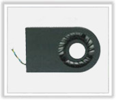
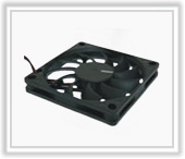
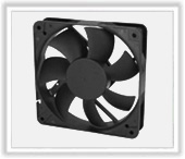
A
wide range of DC fan including Axial fan, blower, Motorized
impeller applications, the sized of
our DC fans range
form 25mm to 290mm
,and the balanced performance fit kinds of application.
DC Fan General Specification :
1.
Operation temperature:
-10 ℃ to + 70 ℃ . (humidity: 35%~85%RH)
2.
Storage temperature:
-40 ℃ to + 75 ℃ . (humidity: 35%~85%RH)
3.
Insulation resistance:
10mega OHM MIN. At 500VDC (between frame and (+) terminal)
4.
Dielectric strength:
5mA MAX. at 500 VAC 60 Hz one minute (between frame and (+) terminal)
5.
Vibration resistance test:
Applied 5.30Hz, 0.04 peak to peak amplitude, 30-500Hz, 2G peak amplitude for five minutes to all three axis.
Fan shall satisfy the specified performance standards.
6.
Shock test:
Under the conditions of 60G , 11 ms (1/2 sine), two times to all three axis, it shall satisfy the specified performances standards.
7.
Protection:
(1)
Impedance protection: The rotor drive shall be restricted for 72 hours in the state where is made in the range of operating
temperature and operating voltage. In shall not fail.
(2)
Locked current protection:DC fan has over current protection circuit with auto restart after after 3 seconds.
8.
Life expected:
Mean endurance time until the revolution drops by 30% of the initial value in the condition of continuously running under standard
environmental condition and rated condition.
9.
Polarity protection:
The fan will not cause damage when reverse rated voltage is connected.
Noise Characteristics:
Noise measurements are central values as measured at a point 1m from the suction surface of a fan suspended and at rated voltage in an
anechoic room with LARSON DAVIS type 824s sound level meter.
Air Flow and Static Pressure Characteristics:
The performance including air flow and air pressure measured at rated voltage in double chamber is measured according to AMCA 210-99 standard as shown below:
Conversion Table:
Static pressure:
Specifications :
Output type: open collect
VFG maximum voltage
◎13.8V as 12V Voltage fans
◎26.4V as 24V Voltage fans
◎56.0V as 48V Voltage fans
Ic maximum current= 5mA
Output waveform :
During normal run
T= T1+T2+T3+T4= 60/N (Sec)
N: SPEED (RPM)
Rotation Detector (RD) Signal:
RD produces fan motor signals. These are best suited for detecting whether the fan motor is running or stopped.
Output type:
open collect
◎VFG maximum voltage
◎13.8V as 12V Voltage fans
◎26.4V as 24V Voltage fans
◎56.0V as 48V Voltage fans
◎Ic maximum current= 5mA
Output waveform (with load resistance connected and pulled up)
Output circuit:
Speed vs. duty cycle :
Specifications :
◎PWM input voltage range: High level= 2.8 to 20 VDC
◎PWM input current range: 40 μ A to 20mA
PWM (pulse width modulation):
In PWM speed control, a fixed frequency square wave is applied to the speed control of the fan.
The ratio of the on time vs. the PWM period is proportional to the RPM.
To control signal line of the fan, the frequency of PWM shall be able to accept a 30 HZ to 30kHz.
The preferred operating point for the fan is 0%~100% duty cycle.
Using Fan by Parnell and Series Arrangement :
Estimate Fan Air flow and Pressure
For identical fans in parallel, P max = P max,single, Q max = Q max,single x no.of fans
Fan Choice by Your System Impendence :
Every system has an impedance curve. System impedance is generally proportional to Q2.
Operating point is the intersection of P-Q curve and the impedance curve. The use of impedance
curves is to select a fan that provides maximum air flow rate at the operating point.